


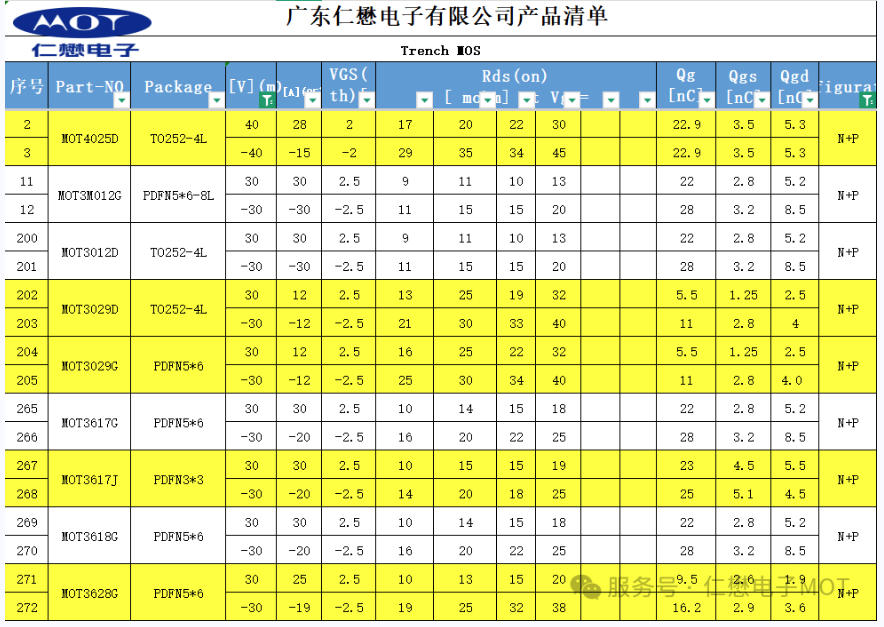
In the motor drive application market, N+P dual Channel MOSFETs employing in motor drive methods commonly can be categorized into the following types:
01 Integrated half-bridge drive:
In high-power square wave motor drive applications, the strong magnetic field environment generated during motor operation poses a severe challenge to the anti-interference capability of power devices. Currently most products on the market, the threshold voltage (Vth) of MOSFET were designed in the range of 1.2V-1.3V. This voltage range is prone to false triggering under strong interference, which can lead to shoot-through short circuits in the upper and lower bridge arms, seriously threatening system reliability.
To address this issue, MOT has specifically optimized the square wave-specific MOSFET to raise the threshold voltage to above 1.5V. This design ensures that the device can conduct reliably at a 7.5V drive voltage while significantly enhancing its anti-interference capability, thereby effectively avoiding the shoot-through risk caused by false triggering.
02 Discrete Component Driving Method:
In driver circuits built with discrete components, the typical architecture uses transistors to drive P-channel MOSFETs, while the N-channel MOSFET is directly controlled by MCU. Since for most MCU, the output levels of GPIO are standard 5V or 3.3V, when the PWM signal passes through an external series drive resistor, the actual drive voltage reaching the MOSFET gate-source (Vgs) typically decays to 3.7V-4V or lower.
This voltage decay can easily cause the MOSFET to operate in a partially conducting linear region, leading to increase on-resistance, and consequently causing device temperature rise. Attempting to lower the turn-on threshold of the N-channel MOSFET to improve conduction may introduce a shoot-through risk during switching, and cause both upper and lower bridge arms to conduct simultaneously, and jeopardize system safety.
See the diagram below for the specific principle.:
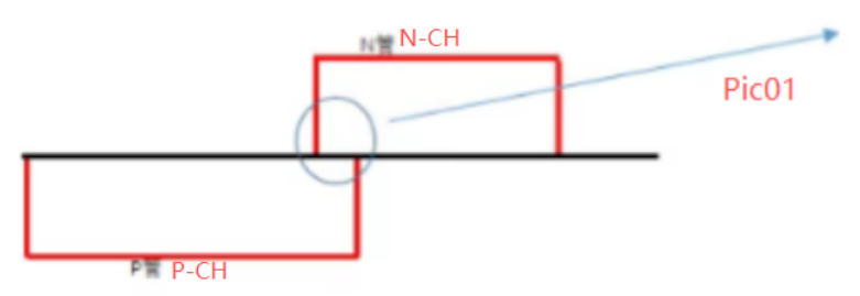
1, When the N+P dead zone crosses, it will cause the N-channel transistor to fail. (Pic 01)
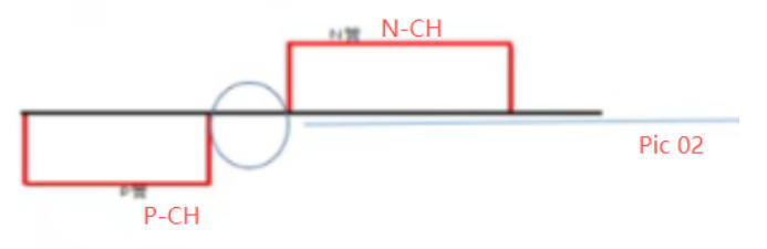
2, When the N+P dead zone is too long, it will cause significant motor vibration and extremely low efficiency.(Pic 02)
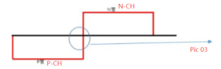
3, The waveform is relatively perfect..(Pic 03)
03 Hardware-driven methods – discrete component-driven methods – often encounter the following problems based on our analysis.
1, Insufficient driving capability: vibration occurs when shutting down.
2, The turn-off time is uncontrollable. Therefore, to better protect the MOSFET, many engineers extend the drive time of the N-channel MOSFET. This is usually achieved by increasing the drive resistor.
3, To address the above issues, MOT increases the turn-on voltage Vth, thus lengthening the turn-off time of the P-channel MOSFET and slowing down the turn-off time of the N-channel MOSFET. This effectively solves the problem of N-channel MOSFET mis-turn-on caused by dead-time crossover and oscillation.

 Headquarter: 19th Floor, SCTC Mansion, Guiyuan Rd, Luohu, Shenzhen, Guangdong
 Contact Phone:+86-755-82527851
